




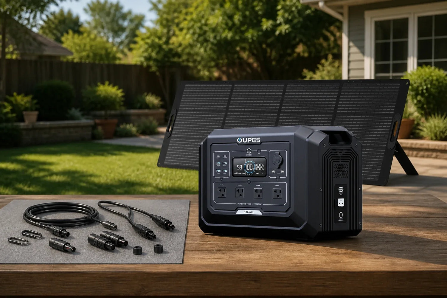
An MC4-style connector is only one part of solar compatibility. A safe connection also requires matching voltage, current, polarity, cable size, connector family, and the input limits of the charge controller or power station. Two plugs that click together are not automatically an approved electrical pair. Start with manuals and labels, then treat every adapter or extension as part of the circuit rather than a harmless accessory.
This guide uses American English and separates permanent solar or building work from portable backup. Product ratings come from the current US regional product table; local permits, contracts, site conditions, and equipment manuals still control the final decision.
What “MC4” Tells You—and What It Does Not
MC4 commonly describes a locking single-contact photovoltaic connector format. The name helps identify the general style, but it does not establish that connectors from different manufacturers are intermateable or that an assembled cable has the rating required by your system. Check the exact connector manufacturer, model, conductor size, voltage rating, current rating, environmental rating, and approved assembly method.
Polarity is equally important. PV modules may use visually similar positive and negative housings, while adapters can reverse or preserve polarity depending on construction. Verify polarity with documentation and appropriate test procedures before connecting equipment. Never infer polarity from cable color alone, especially on third-party extensions or previously modified systems.
Check the Entire Electrical Path
Write down the panel’s open-circuit voltage, operating voltage, short-circuit current, and operating current. Then compare the proposed series or parallel arrangement with the receiving device’s solar-input voltage and current limits. Series wiring raises voltage; parallel wiring raises current. Cold conditions can raise module open-circuit voltage, so a design that barely fits under mild conditions may exceed an input limit in colder weather.
Each extension, branch connector, fuse, adapter, and entry gland must suit the expected current and environment. Longer cable runs increase voltage drop. Undersized conductors can waste energy and create heat. If the required calculation or assembly method is unclear, use a qualified solar technician rather than trial-and-error connections.
Inspection and Safe Handling
Inspect for cracked housings, bent contacts, loose crimps, discoloration, moisture, dirt, corrosion, and damaged locking tabs. The Department of Energy’s PV system weather-vulnerability guide treats damaged PV connector replacement as work for trained electrical or specialized PV technicians and identifies shock and tool hazards. That is a strong reason not to repair energized or unfamiliar PV wiring casually.
De-energize and isolate the system according to its instructions before service. Use the manufacturer-specified crimping and release tools. Do not force connectors apart, cut live conductors, or use tape as a substitute for a weather-rated connector repair. Keep portable connectors off wet ground and protect disconnected ends from contamination.
A Portable OUPES Example
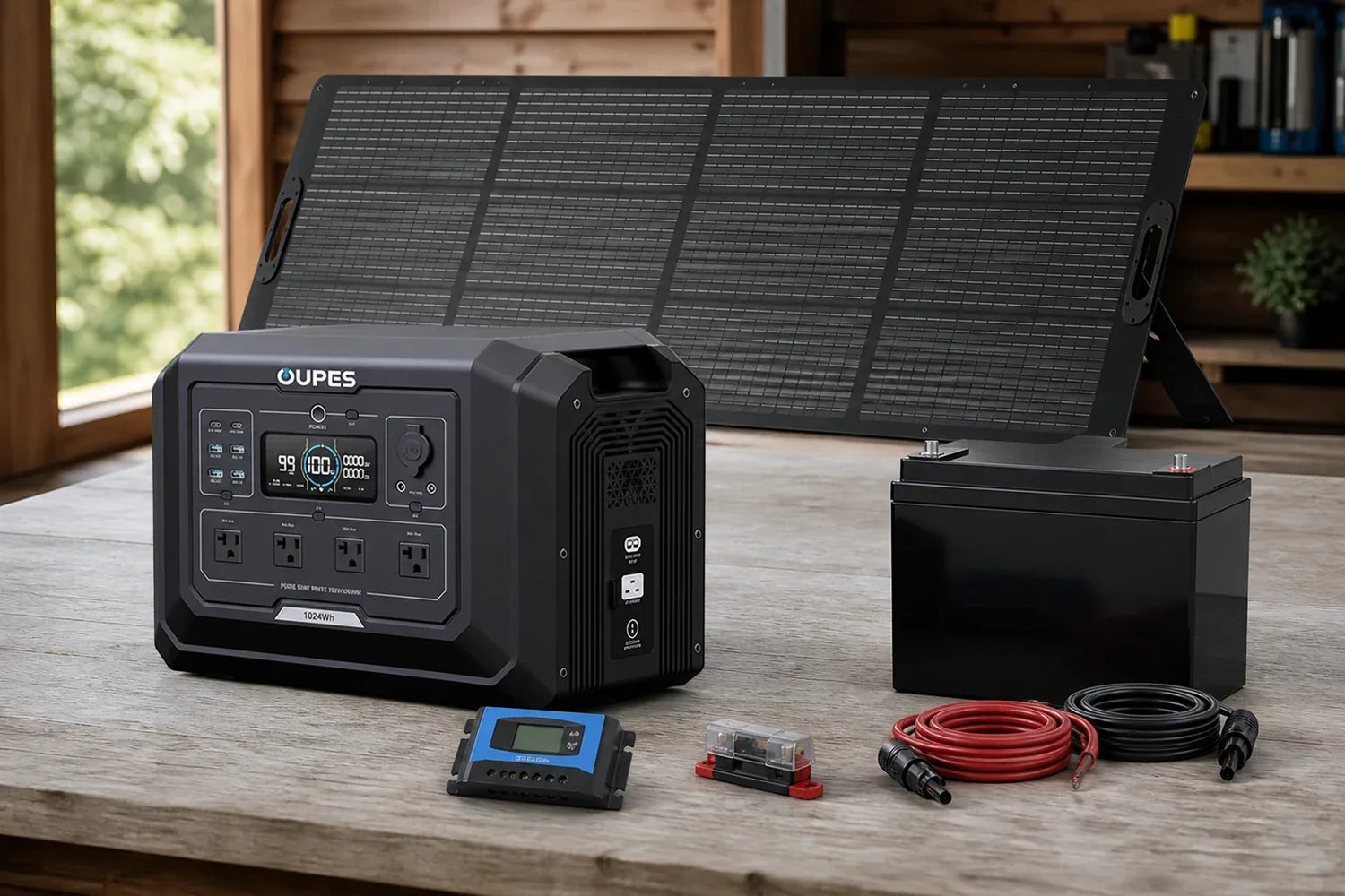
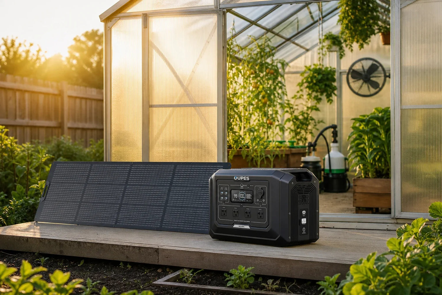
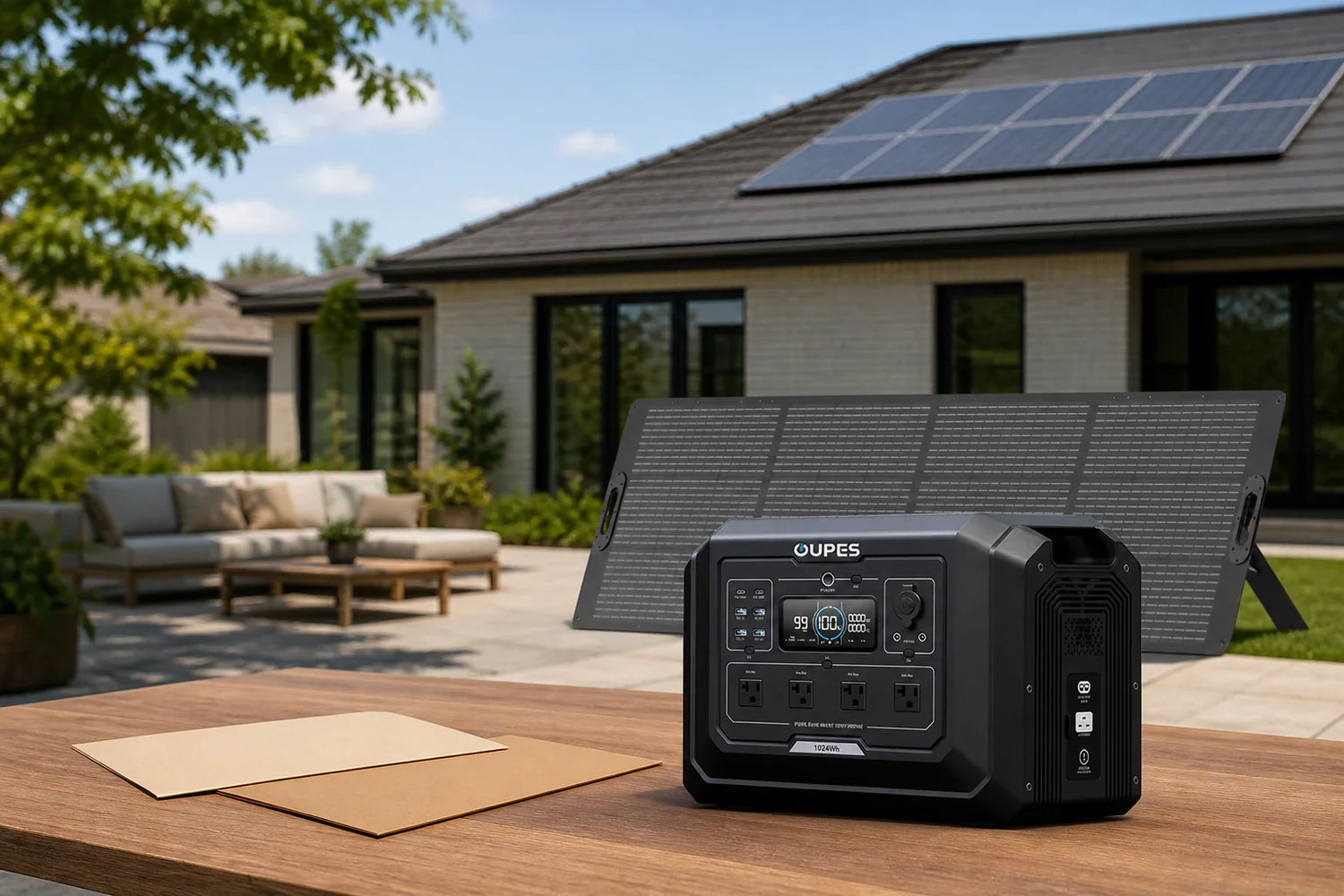
The Mega 1 + 240W Solar Panel Solar Generator Kit combines a 1,024Wh, 2,000W power station with one 240W portable solar panel. The product table lists up to 800W solar input for the power station, but that number does not authorize arbitrary panels, series strings, or adapters. Confirm the kit’s supplied connections and current manual before adding components.
For a portable setup, keep the original cable identification with the kit and review the off-grid power station guide for planning context. If you need a permanent array or building penetration, move the project into professional fixed-system design rather than extending a portable configuration beyond documented use.
Connector Buying Checklist
When purchasing a replacement lead, ask for the exact connector manufacturer and part family at both ends, conductor gauge, length, insulation type, voltage and current ratings, temperature range, and whether the assembly is factory terminated. A listing that says only “solar extension” or “MC4 compatible” leaves important questions unanswered. Confirm whether the equipment manufacturer accepts that assembly without affecting warranty or environmental protection.
For parallel branches, confirm that branch connectors, fusing, and controller current limits support the combined current. For series strings, calculate cold open-circuit voltage from module documentation. In either layout, label cables so the intended configuration can be recreated without guessing. Keep unused caps and release tools together in a dry storage pouch.
Common Connector Mistakes
One common mistake is mating connectors from different brands because they lock mechanically. Another is using an extension with a smaller conductor than the rest of the circuit. Reversed-polarity adapters, poorly crimped field terminals, connectors lying in water, and DC plugs disconnected under load can also create failure points. A connector can look intact while a loose contact is heating internally.
After setup, observe charging power and cable temperature without touching exposed electrical parts. Unexpectedly low input, intermittent charging, odor, discoloration, or a hot connector warrants shutdown and inspection. Do not repeatedly reconnect a suspect plug to see whether it improves. Preserve photographs and component labels for a technician.
Trace the Path From Panel to Power Station
Start at the panel junction box and follow every component to the receiving input. The path may include panel leads, an extension, a branch, an adapter, and the power station’s supplied cable. The weakest rating or an incompatible interface can control the whole path. This trace also reveals whether an adapter is being used to solve the wrong problem, such as attempting to correct excessive voltage.
For the OUPES kit, begin with the included panel and supplied connection described in the current manual. If portability is the goal, an original documented path is easier to inspect, store, and deploy than a chain of third-party adapters. If a permanent run is the goal, use fixed-system components and professional design rather than leaving portable connectors as building wiring.
Power, Capacity, and Solar Production Are Different
Watts describe the rate at which equipment uses or produces power. Watt-hours describe stored or consumed energy over time. A system can have enough energy for a day and still fail to start a motor if its inverter cannot handle the momentary demand. It can also have ample rated output but run for only a short period if the battery is small relative to the load. List continuous watts, possible startup watts, and daily watt-hours separately.
Solar-panel nameplate power is a test-condition rating, not a promise of identical output every hour. Shade, orientation, temperature, clouds, cable losses, controller limits, and season all matter. Use a range for expected production and leave reserve energy for poor weather. When portable panels charge a power station, the station’s documented solar-input limits remain the controlling boundary even if more panel wattage is physically available.
Keep Fixed Solar and Portable Backup in the Right Categories
A roof, carport, greenhouse array, or permanent tiny-house electrical system may involve structural engineering, electrical permits, utility interconnection, grounding, overcurrent protection, and code-compliant wiring. A portable OUPES solar generator is a power station packaged with portable solar charging. It can support compatible plug-in loads, but it should not be described as a grid-tied array, an automatic whole-home system, or a substitute for professional fixed wiring.
That boundary is useful rather than limiting. A fixed array can serve the building’s long-term energy plan, while portable storage can cover selected loads, travel, maintenance outages, or locations where permanent work is not appropriate. Review the US solar generator collection, portable solar panels, and home backup packages as distinct categories instead of assuming that every product solves the same problem.
Use a Repeatable Sizing Workflow
Start with a load inventory. For each item, record rated watts, hours per day, startup behavior, and whether it must run at the same time as another device. Multiply watts by hours to estimate daily watt-hours, then add a reserve rather than planning to empty a battery completely. For thermostatically controlled loads, measure real cycling when practical because a simple nameplate-times-hours estimate may be too high or too low.
Next, compare three constraints in order: connection compatibility, simultaneous output, and energy duration. A connection that does not match cannot be fixed by extra battery capacity. An inverter that is too small cannot be fixed by extra solar panels. A battery that is too small cannot be made dependable by assuming perfect sun. Document each constraint independently and confirm uncertain specifications with the equipment manufacturer.
Plan for Weather, Placement, and Maintenance
Keep portable power equipment dry, ventilated, stable, and within the manufacturer’s temperature limits. Route cables where they will not be pinched, crushed, tripped over, or left in standing water. Inspect connectors for damage and contamination before use. Never disconnect energized DC connectors casually, improvise adapters, or mix components merely because they appear to fit.
Production and load both change with weather. Winter can reduce solar hours while heating-related demand rises; summer heat can increase ventilation or cooling loads. Recheck the energy budget for the hardest relevant season. Store manuals, cable identification, load calculations, and a simple shutdown procedure with the equipment so another household member can operate the setup without guessing.
Frequently Asked Questions
Are all MC4 connectors compatible?
No. Similar locking shapes do not guarantee manufacturer-approved intermating, equal ratings, or a weather-tight connection. Match the exact connector family and follow both equipment manuals.
Can I use an MC4 extension cable?
Only when its connector family, conductor size, length, current, voltage, and environmental ratings suit the circuit. Account for voltage drop and protect the cable from damage.
Does an MC4 adapter change voltage?
A passive adapter normally changes the physical connection, not the electrical voltage. It can change polarity or introduce a new current limit, so verify its wiring and rating.
Can I connect panels in series?
Only if the combined cold-weather open-circuit voltage remains inside the receiving device’s input range and the panels and connectors are approved for that configuration.
Should I disconnect solar connectors in sunlight?
Avoid breaking an energized DC circuit unless the documented procedure explicitly permits it. Isolate or de-energize the system first and use the proper release tool.
What should I check before charging an OUPES unit?
Confirm the exact model manual, supported voltage and current range, polarity, supplied cable, connector condition, panel configuration, and a dry, ventilated operating location.
Conclusion
A reliable solar panel with MC4-style connectors is a verified electrical system, not a collection of plugs that happen to fit. Match every rating, preserve polarity, inspect the cable path, and keep fixed installation work with qualified professionals. The OUPES kit offers a documented portable starting point, while any expansion should remain inside the current manual’s limits.
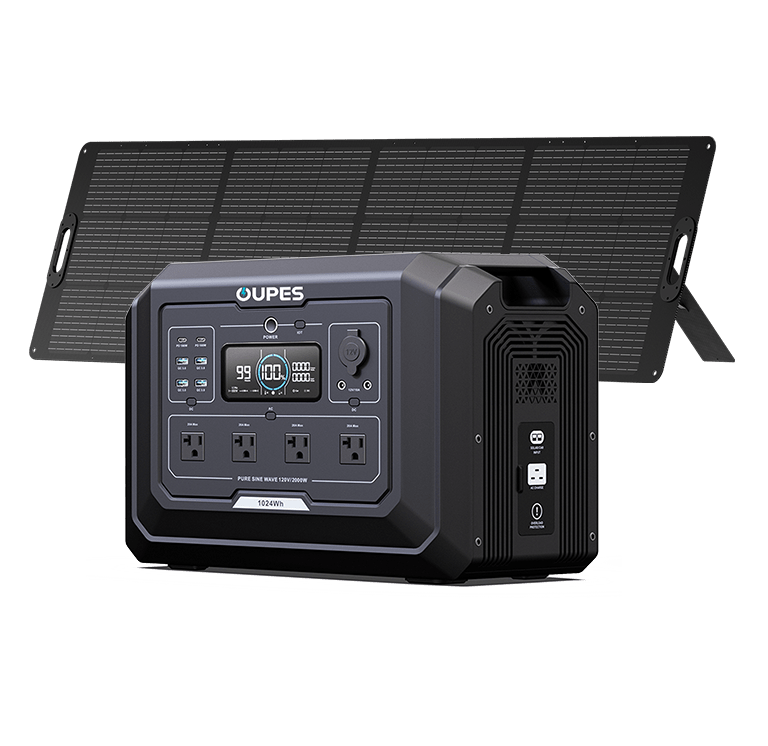
Mega 1 + 240W Solar Panel Solar Generator Kit
- Mega 1 with one 240W portable solar panel
- 1,024Wh capacity
- 2,000W rated output
- Up to 800W solar input

Leave a comment
This site is protected by hCaptcha and the hCaptcha Privacy Policy and Terms of Service apply.